LII:Basic Physics of Nuclear Medicine/Dynamic Studies in Nuclear Medicine
Introduction
[edit | edit source]This is a developing chapter of a Wikibook entitled Basic Physics of Nuclear Medicine.
The metabolism of a substance in the human body is the result of a number of inter-related dynamic processes which include the absorption, distribution, utilization, degradation and excretion of the substance. The measurement of just one of these parameters can give a result which is indicative of a disease, but may not identify the actual cause of the disease. More detailed information about the cause may be determined when knowledge of the complete metabolic system is obtained. One method of gaining such knowledge is through mathematical simulation of the physiological system. The outcomes of this approach include generating a representation of the entire system as well as an understanding of interactions between its component parts. The approach typically involves:
1. obtaining experimental data following stimulation of the system by addition of a suitable tracer,
2. comparing experimental data with data predicted by the mathematical simulation, and
3. varying parameters of the simulation until the two sets of data agree as closely as possible using methods such as least squares, maximum likelihood and Monte Carlo simulation.
The general assumptions for this approach are that:
- the addition of the tracer does not perturb the system,
- the tracee (i.e. the substance under investigation) is conserved throughout the process,
- the tracer is conserved throughout the process – allowing for radioactive decay, and
- the system is in a steady state (i.e. the amount of tracee in each compartment of the system remains constant as does the exchange of tracee between each compartment).
There are two major types of mathematical model in use:
- Deterministic: where analytical expressions are used to describe the exact behaviour of the tracer in each part of the system with time. The mathematical expressions used are usually exponential or power functions,
- Stochastic: where the behaviour of the system is determined by random processes which are described by probability functions.
Deterministic models are considered in some detail below.
Compartmental Analysis
[edit | edit source]This form of deterministic analysis involves dividing the physiological system into a number of interconnected compartments – where a compartment is defined as any anatomical, physiological, chemical or physical subdivision of a system. A basic assumption is that the tracer is uniformly distributed throughout a compartment. The simplest of such systems to consider is the single compartment model. We will start our treatment with this simple model and then extend it to more complex ones – the initial ones being considered simply to develop the framework with the later ones providing direct relevance to nuclear medicine dynamic studies; their acquisition and analysis.
There is an ImageJ plug-in available, named Compartments_TP, which provides simulations of a number of additional models.
Single Compartment Model
[edit | edit source]The flow of a tracer through a blood vessel following an ideal bolus injection is shown in the following figure as an illustration of a single compartment model. The compartment illustrated is closed except for the inflow and outflow of the tracee, and the tracer is injected as indicated. In these theoretical conditions, the tracer will mix immediately and uniformly throughout the compartment following its injection. And its quantity will reduce with time depending on the rate of outflow. The variables used in the figure are:
F: the outflow.

We can define the fractional turnover, k, as the ratio of these two parameters, i.e.
which can be rewritten as:
Without going into the mathematical details (which are similar to the derivation of the radioactive decay law!), the solution to this equation is:
where qo is the quantity of tracer present at time, t = 0.
This equation is plotted below to illustrate the influence of the value of the fractional turnover, k:

<
The graph indicates that the quantity of tracer in the compartment will decrease exponentially with time following injection at a rate dependent on the outflow, as might be intuitively expected.
Two Compartment Model – Closed System
[edit | edit source]A more complex, and yet still relatively simple, set of models are those based on two compartments. In a closed system the tracer simply moves between the two compartments without any overall loss or gain – see the following figure:

Therefore,
| and | . |
Since there is no loss of tracer from the system,
Therefore,
indicating that as the quantity of tracer in Compartment #1 decreases, the quantity in Compartment #2 increases, and vice versa. Now, consider the situation illustrated in the figure above, where the tracer is injected into Compartment #1 at time, t = 0. At this time,
| and |
and, initially,
| and |
The solutions to these equations are:
and
and their behaviour in the special case when k12 = k21, and the volume of the two compartments is the same, is illustrated below:

Note that this model predicts that a steady state will be reached as the quantity of tracer in Compartment #1 decreases exponentially and the quantity in Compartment #2 increases exponentially, with the rate of each change controlled by the sum of the turnover rates.
Two Compartment Model – Open Catenary System
[edit | edit source]This is an extension of the single compartment model considered earlier with two compartments connected in series, as shown in the following figure:
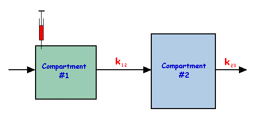
In this model,
| and |
The solutions to these equations are:
and
and the behaviour of q1 and q2 is shown in the figure below for the special case of k20 being three times the value of k12:

Note that the behaviour of q2 in this figure is similar to arterial tracer flow following an intravenous injection, and to the cumulated activity parameter used in radiation dosimetry.
Two Compartment Model – Open Mamillary System
[edit | edit source]This model is equivalent to the closed two compartment system considered above with the addition of an outflow from one compartment:

In this case,
| and |
At t = 0:
| and |
and, initially
| and |
The solutions to these equations are:
and
where
| and |
The behaviour of q1 and q2 is illustrated in the figure below:

This model has been widely adopted in the study of:
- metabolism of plasma proteins, where Compartment #1 is the plasma and Compartment #2 is the extravascular space,
- trapping of pertechnetate ion in the thyroid gland, where:
- Compartment #1: the plasma,
- Compartment #2: the thyroid gland,
- k12: clearance rate from plasma into the gland, and
- k21: leakage rate from the gland into the plasma.
Models with Three Compartments
[edit | edit source]The open mamillary model above has been extended to study iodine uptake using a third compartment which is fed by an irreversible flow, k23, from Compartment #2:

where:
- Compartment #1: the plasma,
- Compartment #2: the trapping of inorganic iodide in the thyroid gland, and
- Compartment #3: iodide within the gland which has become organically bound as part of hormone systhesis processes.
The open mamillary type of model has also been applied to renal clearance with the system consisting of an intravascular compartment, with an extravascular compartment exchanging with it and connected irreversibly with a urine compartment:

The intravascular compartment (#1) in the figure above represents tracer which is exchangeable with the renal parenchyma and the extravascular space. The urine compartment (#2) represents tracer which has been cleared by the kidneys and is therefore associated with the renal pelvis and the bladder. The extravascular compartment (#3) represents the tracer which has not been cleared, e.g. tracer which becomes bound to other molecules or tracer in extrarenal tissues.
When the tracer is injected into the intravascular compartment via a peripheral vein, the initial distribution will not be uniform throughout the body – but this non-uniformity will even out as the blood circulates. For a highly vascular region, a plot of the quantity of tracer versus time will show an initial sharp rise which will rapidly fall off. The magnitude of this spike will vary with:
- the anatomical region,
- the site of the injection, and
- the speed of the injection.
Compartmental analysis cannot therefore be applied to this phase of a renogram since the basic assumption of uniform tracer distribution, implicit in compartmental analysis, cannot be applied.
Following this phase, the quantity of tracer in the intravascular compartment begins to fall because of:
- uptake by the kidneys – represented by k12 in the figure above,
- diffusion into the extravascular space – represented by k13.
As the quantity of tracer in the extravascular compartment builds up, exchange in the opposite direction begins to occur (represented by k31), and so a maximum is reached before its quantity of tracer falls off. This is illustrated in the figure below for a situation where:
| k12 = 0.05 per minute | k13 = 0.04 per minute | k31 = 0.06 per minute |
| l1 = 0.13 per minute | l2 = 0.024 per minute | |
| A1 = 0.65 | A2 = 0.35 |

Ultimately, all the tracer will end up in the urine compartment.
The equations used for the figure above are:
where l1 and l2 are constants related to the fractional turnovers, and A1 through A5 are also constants such that:
| and |
In practice, the renal clearance can be obtained by monitoring the quantity of tracer in the intravascular compartment, e.g. the blood plasma concentration, P, where:
The time dependence of this plasma concentration will vary in the same way as q1, so that:
where C1 and C2 are related to A1 and A2, respectively. The renal clearance, which is related to k12, can therefore be determined by characterizing the biexponential fall off in the quantity of tracer in the intravascular compartment.
Glomerular Filtration Rate
[edit | edit source]The Glomerular Filtration Rate (GFR) is generally regarded as one of the most important single indicator of renal function. It is particularly important in assessing the presence and severity of kidney failure.
There are three major methods of determining a patient's GFR:
- Inulin clearance,
- Creatinine clearance,
- Radiotracer clearance.
Inulin clearance has been used for many years and is often regarded as the most reliable and accurate of the three methods. Its major disadvantages however include the need for continuous intravenous infusion, timed urine collections via a bladder catheter and protracted chemical analysis. Creatinine clearance has been widely used for routine GFR assessment as a result. However, while this method gives similar results as inulin clearance under normal conditions, the validity of its results is questionable in patients who have moderate to advanced renal failure because of an increasing significance of tubular secretion.
The third method, radiotracer clearance has been widely adopted using 51Cr-EDTA. This tracer is known to be physiologically inert, not bound to plasma proteins and not metabolized by erythrocytes or organs other than the kidneys. It is normally excreted within 24 hours of injection, 98% via the kidneys. 51Cr has a half-life of about 28 days and decays by 100% electron capture into stable vanadium, emitting monoenergetic (320 keV) gamma-rays in about 10% of the transformations. In addition, 51Cr-EDTA determination of GFR can be used in conjunction with OIH renal plasma flow assessment for the differential diagnosis of various renal conditions.
The typical radioactivity administered for 51Cr-EDTA clearance is 1-10 MBq and the radiopharmaceutical is generally administered via intravenous injection. This Single Shot technique assesses the GFR through venous blood sampling, in the simplest case, or by continuous external monitoring of the gamma-rays from 51Cr in the more sophisticated approach. When the patient counts are plotted against time on a log/linear axis, a curve is generated which falls off rapidly at first and thereafter decreases at a constant rate, representing the behaviors of q1 is our last figure. This initial fall-off arises as a result of the establishment of an equilibrium between the radiotracer and the extravascular, extracellular fluids. The slower second phase reflects renal excretion and contains the information necessary for GFR assessment.

A quick and simple technique is to obtain two blood samples from the patient, one at two hours and the other at four hours post injection. The counts per unit volume in the plasma of each sample are determined using a scintillation counter and compared with the counts from a standard solution. The standard solution is made by diluting an injection, identical to the patient's, in a known volume of water, e.g. 1 liter.
The slope, m, of the second portion of the above curve can be determined from:
where:
- t1: time from injection for the first blood sample, usually 120 minutes,
- b1: counts per milliliter (mL) in the plasma from the first sample (corrected for background counts),
- t2: time from injection for the second blood sample, usually 240 minutes,
- b2: counts/mL in the plasma from the second sample (also corrected for background).
We can now extrapolate this straight line back to the time of injection, t0, to determine what the plasma counts would be upon instantaneous mixing of the tracer throughout the patient's plasma compartment, i.e.
as illustrated in the following figure:

Therefore, we can write:
The Dilution Principle can now be used to determine the volume of this plasma compartment by comparing the plasma counts with those from the standard solution, i.e.
which results in
when the standard injection is diluted in 1 liter. The clearance (in ml/min) is then given by the following equation:
Results for two patients are shown below to illustrate this technique.
Patient A
| Sample | Counts/mL |
|---|---|
| Background | 477 |
| b1 at 119 mins | 11,438 |
| b2 at 238 mins | 6,235 |
| Standard, S | 150,020 |
This patient's 51Cr-EDTA clearance was determined to be 38.8 mL/min. This result was assessed to be indicative of chronic renal failure, which was later found to be due to lupus nephritis. The patient was then placed on steroid therapy.
Two months later the patient was re-tested and the clearance was found to have risen to 52.7 mL/min. For the patient's age, this clearance was gauged as within the normal range indicating that the therapy was having a positive effect. The therapy was then ceased. Two months further, the patient was again tested having been without steroid therapy for this period. The result was 54.2 mL/min reflecting successful treatment.
Patient B
| Sample | Counts/mL |
|---|---|
| Background | 425 |
| b1 at 122 mins | 3,103 |
| b2 at 250 mins | 1,390 |
| Standard, S | 104,600 |
This patient had a high blood pressure and a renal involvement required confirmation. The clearance however was 117.3 mL/min, which is well within the normal range. The kidneys were therefore excluded from the investigation of this patient's condition.
Note that the number of blood samples is not limited to two, with some methods requiring three, four or more samples, and other methods using external monitoring of the clearance. Each method is nevertheless based on the form of analysis outlined above where the rate constant of the second phase of the clearance curve is determined along with the volume of distribution of the radiotracer. The timing of blood sampling is therefore after the first phase has finished, i.e. more than about two hours following injection, with the volume of distribution determined using a single-exponential fit to this later phase.
It is important to appreciate that the clearance of 51Cr-EDTA determined as described does not equate directly with the Glomerular Filtration Rate (GFR) since the method assumes a single exponential dependence. 51Cr-EDTA clearance results are therefore typically corrected by a factor, either empirically- or theoretically-derived, to force them to express the true GFR. Empirically-derived corrections include those of:
- Chantler (1969), where the 51Cr-EDTA clearance is multiplied by a factor of 0.8;
- Brien (1969), where clearances above 50 mL/min are multiplied by 0.82 and added to 6;
- Brochner-Mortensen (1972), where a second-order polynomial is applied
to obtain the GFR. A correction based on a theoretical consideration of the relationship between true GFR and single-exponential clearance values based on compartmental analysis has been introduced (Fleming, 2007) which gives improved corrections, especially at high GFRs. This correction is of the form:
where = 0.0017 min/mL.
As a final step, corrected clearance measurements are generally standardized to the body surface area (BSA) of the Standard Man, i.e. 1.73 m2. This is typically done using estimates of the BSA based on the patient's height and weight – as derived from DuBois (1916) or Haycock (1978), for instance. A single-exponential correction technique, based on BSA-scaled clearances has also been introduced (Jodal & Brochner-Mortensen, 2008) which is similar to that of Fleming (2007) but provides improved correction in paediatric studies.
Renography
[edit | edit source]It should be apparent from the discussion above that the urine compartment (#2) consists of the quantity of the tracer in the urine, without distinguishing whether the urine is in the renal pelvis, the ureters or the bladder. These anatomical spaces can be incorporated by extending the three compartment mamillary model to five compartments:

Note that the passage of the tracer through the renal parenchyma can be characterized by a transit time, t0, and that k56 is related to the rate of urine production.
The solutions to the resultant differential equations for the quantity of tracer in the renal parenchyma, the renal pelvis and the bladder incorporate consideration of the time delay, t0, so that:
- When t < t0:
- When t > t0:
where l3 is related to k56. The time course of the quantity of tracer in each compartment is shown below:

The quantity of tracer in the overall kidney can be obtained by summing the renal parenchyma and renal pelvis curves, so that:
as shown below:

What is recorded in a renogram in practice is not just this kidney curve, but also the quantity of tracer in:
- overlapping and underlying tissues, and in
- the intravascular space of the kidney itself.
These contributions add a background upon which the true renogram is superimposed. The quantity of tracer in this background varies with time, but not in the same way as the true renal curve. The time course of this background is likely to behave in a manner similar to the sum of the intravascular (q1) and extravascular (q3) curves derived earlier using this five compartment model.
The following equation can be derived on this basis:
where b1 and b3 represent the contributions to the detected renogram curve from the tracer in the intravascular and extravascular spaces, respectively. For example, the curves below were generated using b1 = 0.05 and b3 = 0.02 and

In practice, this background curve should be subtracted from the raw renogram data to obtain a curve which reflects the true quantity of tracer in the kidney (see the previous figure). This process is sometimes referred to as blood background subtraction – although you should now be able to appreciate that this is a bit of a misnomer!
The uncorrected and corrected curves are shown below to assist with direct comparison:

and an example from a patient's 99mTc-DTPA renogram is shown in the following figure, to assist you in comparing them with the predictions from compartmental analysis:
 |
 |
A final figure illustrates a form of analysis that can be used in 99mTc-MAG3 renography in a patient with obstructive uropathy:

Background Subtraction in Renography
[edit | edit source]In practice, the background activity in a renogram must be taken into account when interpreting a renogram. This is generally achieved by estimating the background activity and subtracting it from the raw renogram data. The question is: how can this background activity be measured?
One method has been based on recording the activity at nephrectomy sites in patients whose remaining kidney is being examined. However, it should be noted that removal of a kidney also removes an intravascular source of the background activity. As a result nephrectomy sites commonly appear colder than the extra-renal tissues in renogram images.
A potentially better method is to record the activity in the region of a non-functioning kidney.
In most patients, however, a non-renal region must be used for background estimation. Ideally, the choice of region should reflect the same intra- and extravascular background as the kidney itself. There appears to be no standardization in this area, with practices including the use of a region between the kidneys, above the kidneys, over the heart and below each kidney.
A comparison of such methods is provided in Taylor et al (1997) [1] and results of a similar, but more basic, analysis are summarised below:


These renographic images were generated using Monte Carlo simulation[2] and analysed using OsiriX. Split function was calculated using the Integral of counts in the 90-150 second time period. The Mean Absolute % Error was computed from a series of such simulated images where the left kidney to right kidney split function varied from 100%:0%, through 50%:50% to 0%:100% in steps of 5 percent[3].
It is seen that the Lateral RoIs yielded the lowest % Error and that the Central RoI, which was used in the early days of gamma-camera renography using 99mTc-DTPA, yielded a substantially greater error of ~12%. This is in line with current clinical practice where central RoIs are not longer used and lateral or oblique, or perirenal, RoIs are preferred.
In comparison, no background correction generated an error of 20.7%, which highlights the overall importance of background correction.
The variation of background activity is illustrated below for a real LK:RK split function ratio of 50%:50% and for the extremes of 100%:0% and 0%:100%.


The first point to note is that the background curves vary with time in a manner which reflects the renal curves themselves, quickly rising during the uptake phase and falling slowly during the excretion phase. Secondly, note that the right kidney (RK) curves decrease more slowly that those of the left kidney (LK) – possibly as a result of retention of the MAG3 tracer in the liver. This is quite different to the assumption used in the earlier analytical model. The extent of liver involvement can be gauged from the Monte Carlo simulated AP renogram[2] on the left where a reasonable view of the liver and its dynamics can be observed throughout the study. This is consistent with the pharmacokinetic model which was used to generate the virtual study[4].
Thirdly, note that the RK curves are of greater magnitude than those of the LK at 50%:50% and 0%:100%, while the opposite is the case at 100%:0%. This highlights the requirement to use separate background RoIs for each kidney.
The final point to note is in relation to the 90-150 second time window, where the Integral or Slope method is typically applied. It can be seen that both the sum of background counts (the Integral) and the rate of change in these counts (the Slope) vary during this period, which indicates that both methods will be influenced by these features of the background curves.
Once the background region is selected and the activity/time curves are generated, the background curve should be scaled by a factor dependent on the relative areas of the background and renal regions, prior to subtraction from the raw renogram curve. In addition, note that some practices also involve further scaling of the background curve depending on the kidney location. Finally, more sophisticated methods of background correction have been developed and include:
- the generation of interpolated background regions from samples of the background around the kidney,
- the estimation of background correction factors using extrapolation techniques, and
- deconvolution analysis.
It should be noted that caution should be used in translating these results directly to real patient studies in that the raw data is derived from a two-dimensional representation of a compartmental model.
Relative Renal Function
[edit | edit source]The relative function of a patient's kidney is generally defined as that kidney's renal clearance rate expressed as a percentage of the patient's overall renal clearance rate, i.e.
| and |
where LK and RK refer to the left and right kidneys, respectively.
Suppose that:
- NKidney(t): background corrected renal count rate, and
- NBgd(t): count rate from an intravascular region of interest.
It should be apparent at this stage that:
| and |
We can therefore conclude that in the initial phase of the renogram, i.e. when t < t0:
where UC in the kidney uptake constant. This constant is related to that kidney's clearance rate, and we can therefore write:
and
However, we have already seen above that the background corrected renal count rate is directly related to the uptake constant and we can therefore conclude that:
| and |
Note that this analysis indicates that relative renal function can be determined from measurement of the relative counts in each kidney following the initial vascular spike but prior to the commencement of the excretion phase.
Kidney Depth Correction
[edit | edit source]Given that two kidneys can be at different depths within a patient, a correction for the difference in photon attenuation is generally applied. The conventional way of doing this is to acquire lateral views following a renogram so as to measure the depth of each kidney and to apply an exponential correction based on an assumed linear attenuation coefficient for the gamma ray energy (e.g. 0.153 cm-1 for 99mTc gamma rays).
The situation is illustrated by the following study where the right kidney is slightly over 1 cm deeper than the left. The study is actually of images generated by Monte Carlo simulation of a digital phantom (XCAT) which includes the effects of photon attenuation, scattering, limited spatial resolution and noise[2]. The left kidney is positioned 7.31 cm deep while the right is at a depth of 8.64 cm, and the split function is 50:50.
| [[File:nm14 301e.gif|thumb|center|A virtual renogram acquired at 10 seconds per frame for 120 frames. Raw data courtesy of dynamicrenalstudy.org|alt=A virtual renogram. |  |
 |
Note that the two curves do not overlap, as would be expected for a 50:50 split function, as a result of the difference in attenuation. The split function estimated by the integral of counts between 90 and 150 seconds is 54:46. When this attenuation difference is corrected, however, the following curves are obtained and the split function estimate is now a more realistic 49:51.
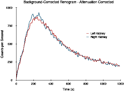
Commercial renal analysis software typically provide options for the automatic computation of kidney depth based on empirically derived relationships between the patient's height and weight and the depth of each kidney. One such package provides the following options (with weight expressed in kg and height in cm):
| Method | Left Kidney Depth (cm) | Right Kidney Depth (cm) |
|---|---|---|
| Standard[5] | 13.2*(Weight/Height)+0.7 | 13.3*(Weight/Height)+0.7 |
| Emory[6] | 16.17*(Weight/Height)+0.027*Age(years)-0.94 | 15.13*(Weight/Height)+0.022*Age(years)+0.077 Note: contains a typographical error[7] |
| Itoh[8] | 14.0285*(Weight/Height)0.7554 | 13.6361*(Weight/Height)0.6996 |
| T.Itoh | 17.05*(Weight/Height)+0.13 | 16.55*(Weight/Height)+0.66 |
A graphical representation of the difference in kidney depth generated by these equations for a broad range of weight-to-height ratios is shown in the figure below (note: an age of 50 years was assumed for the Emory formulae):

It can be seen that little change in depth is predicted by the Standard formulae and that derived attenuation corrections are likely to have little effect on relative function estimates. It can also be seen that the T.Itoh formulae indicate that the right kidney is always deeper than the left. The final two sets of formulae indicate that the right kidney is deeper for weight-to-height ratios of less than 0.6 to 0.7 and the left kidney is deeper above this ratio range. The overall range of depth differences predicted by these latter three formulae is seen to be no more than ±5 mm. Such differences yield an anticipated attenuation correction factors in the range 0.95 to 1.05.
The predictions of these formulae should be contrasted with the results of studies of kidney depth which have shown that differences of greater than 5 mm can be expected in about 60% of patients, and greater than 1 cm in about a third of patients[9]. It can therefore be inferred that the above formulae will only provide sufficient attenuation correction in less than half of patients, and that attenuation correction factors as low as 0.6 can occasionally be expected.
It is therefore apparent that accurate kidney depth measurement is imperative for the proper interpretation of all renograms, and that automatic kidney depth formulae should be applied with caution.
Semi-Automatic Methods of 99mTc-MAG3 Renogram Analysis
[edit | edit source]Commercial software for renogram analysis generally provides a number of methods for what is called semi-automatic analysis – where some features of the analysis require user interaction (e.g. kidney identification) and others are performed automatically (e.g. computations) to determine split renal function and Effective Renal Plasma Flow (ERPF). Here the software might request the user to, for instance:
- input the height and weight of the patient – so that body surface area and kidney depths can be computed using empirically-derived formulae, and
- define regions of interest (RoIs) around each kidney – with background regions automatically placed adjacent to these kidney RoIs.
Counts/time curves are generated for each of these four RoIs. The counts in the background RoIs are then scaled automatically to those of background areas of the same size as the respective kidney RoI and the scaled background curves are subtracted from the kidney curves to generate a net renogram curve for each kidney.
The counts in a pre-defined time interval in the uptake phase of each renogram (e.g. 1 to 2 minutes post-injection) are then used to compute:
- the sum of counts (called the Integral) and/or
- the rate of increase in counts (called the Slope)
for each kidney.
A comparison of these two methods was performed using the Lateral RoIs for background subtraction of the renographic series used earlier, and the 90 to 150 second period for analysis. Both methods yielded very similar results:

|
 |
The Integral method, however, generated a mean absolute % error of just 2.6%, while the Slope method generated a substantially greater error of 9.4% - mainly due to inaccuracies at the lower and higher LK/RK ratios.
In comparison, no background correction generated an error of 20.7% using the Integral method while with the Slope method the error was just 9.2%. This highlights, once again, the importance of such corrections.
The Integral can be corrected for tissue attenuation using the computed depth of each kidney and an assumed linear attenuation coefficient for 99mTc gamma rays. Computation of the Integral in this manner is a major source of error in this form of analysis since the use of the patient’s height and weight (along with their age in one method) to determine kidney depth is likely to be inaccurate – see the previous section. In addition, no standard exists for the value of the linear attenuation coefficient (μ) in the renographic scanning situation, with values such as 0.12[10], 0.14[11] and 0.153[10] per cm in clinical use. For a kidney depth of 6 cm, for instance, these values of μ would result in correction factors of between 2 and 2.5 being applied, i.e. to give a variation of ~20%.
Split Function can be determined from the percentage contribution of each kidney’s Attenuation-Corrected (AC) Integral to the sum of the two kidneys’ AC Integrals.
In addition, Kidney Uptake can be determined by expressing the AC Integrals as a percentage of the injected dose.
Effective Renal Plasma Flow (ERPF) may then be calculated on the basis of empirically-derived formulae such as:
and
Alternatively, a Washout Coefficient can be defined as:
to be multiplied by an estimate of the Plasma Volume, such as:
to give the Total MAG3 Clearance. This final factor is used to calculate the Total ERPF (mL/min) using the formula:
A figure of 0.53 has also been used as an ERPF Conversion Factor[14], i.e. to convert from ERPF to MAG3 Clearance. However, it should be noted that values of this Factor between 0.61 and 0.9 have been reported [13].
As an alternative to these Integral-based methods, the slopes of the curves for each kidney during the uptake phase of the renogram have been used to define a Slope Index for each kidney, based on the Slope of each renogram, attenuation-corrected for kidney depth, and expressed as a percentage of the injected dose multiplied by 106! Split Function can then presumably be obtained by relating the Slope Index for each kidney to the sum of Slope Indices – and the Total MAG3 Clearance calculated using the formula:
Body Surface Area (BSA) estimation is another source of variation in these computations. It is widely used to reference a patient’s ERPF to a standard BSA, e.g. 1.73 m2. It is also used within calculations using formulae such as the one above. At least two BSA computation methods are used in this field, as detailed below:
and
where W is the patient’s weight in kg and H is their height is cm, to give the BSA in m2. These formulae give reasonably similar BSA estimates for adults, e.g. a difference of ~2%, for a 69 kg, 163 cm patient, and their choice as a result is reasonably inconsequential in this application, irrespective of their accuracy.
In summary, commercial semi-automatic renal analysis software is generally based on one of the following two approaches:
- determine the absolute uptake of MAG3 for each kidney and relate these uptakes to the ERPF using empirical relationships derived from limited patient studies (36 presumably-Japanese patients in the case of Itoh et al.[12] for instance);
- determine the rate of MAG3 uptake for each kidney and relate these rates to MAG3 clearances empirically-derived from limited patient studies (12 presumbly-Japanese patients in the case of Oriuchi et al.[13]).
An evaluation of the accuracy of these methods is warranted given the strong empirical features which are evident and the very limited number of patients surveyed. Such an evaluation can be conducted using Monte Carlo simulated renograms [2] and results of such are shown in the following table:

For this evaluation, the formulae for the Itoh ERPF (MAG3), Inoue (MAG3 Without Samples) and Oriuchi Clearance (MAG3) methods [10] were used to calculate the MAG3 Clearance and Split Function for each renogram using spreadsheet software. The values of these parameters for the ERPF Modified Schlegel and ERPF Modified Gates methods were calculated using the manufacturer's software package directly[11] and assumed an ERPF Conversion Factor of 0.76 (i.e. the mean value of Oriuchi’s study [13]) – as did the Itoh[12] method.
It is apparent that no correlation in any of the results exists except, for instance, that when the MAG3 Clearance is halved from 260 to 130 mL/min, the computed clearances also reduce – although the results for the Modified Schlegel method are quite reasonable in some situations. A second point is that the variation in split function estimates is likely to result in part from the use of (potentially inaccurate) automatic methods of kidney depth determination.
So.... should these automatic computations be used clinically without, for instance, a confirming set of kidney depth measurements from lateral scans, post-renogram, or from an ultrasound scan? This question was answered in 1985[9] but unfortunately has not yet seemed to infiltrate the psyche of producers of modern renal analysis software.
Another question: should conjugate imaging be considered for renogram analysis in commercial dual-headed gamma camera software packages?
Conjugate Imaging in Renography
[edit | edit source]The principle of conjugate imaging is based on computing the Geometric Mean of activity measurements from two opposing detectors and is illustrated in the following diagram where a homogeneous medium (yellow rectangle) containing a point source of radioactivity (red dot). The thickness of the medium is d and the point source is a distance t1 from Detector #1 and a distance t2 from Detector #2.

The activity detected by Detector #1, assuming no scatter is detected, is given by:
while that detected by Detector #2 is given by:
The Geometric Mean, GM, of the detected activities is given by:
so that:
and, therefore:
and, as a result:
This final equation indicates that the Geometric Mean is dependent solely on the thickness of the medium, d, which contains the point source and not on the distance of the source from either detector.
Translating this to renography implies that imaging with opposing gamma camera heads (as with a dual camera SPECT system) would provide spilt function measurements which are independent of renal depth.
Conjugate imaging in renography is illustrated by the following images [2] of Monte Carlo simulated renograms acquired simultaneously using anterior-posterior (AP) and posterior-anterior (PA) projections. The simulations had renal depths of 7.31 cm on the left and 8.64 on the right and the real LK/RK split function ratio was 50%:50%.
 |
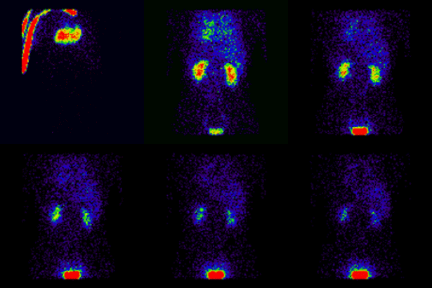
Geometric Mean renogram |
 |
These images were used to compute the Geometric Mean using ImageJ and the resultant images were analysed using OsiriX. Image computation involved multiplying the AP and PA renograms and taking the square root of the result, at 32-bit accuracy. Computed images were the converted to 16-bit for DICOM storage. The resultant Geometric Mean renogram (see the centre panel above) provided an LK/RK split function estimate of 51%:49%, while the PA-only data, not corrected for renal depth, provided an inferior estimate of 54%:46%.
It is apparent from the above illustration that conjugate imaging may have a role in clinical renography and may not be reliant on renal depth measurements for attenuation correction. However, it should be noted that the method assumes that the activity is located in a homogeneous medium with a spatially-uniform linear attenuation coefficient, μ, which indicates that the method may suffer in real patients from aberrations generated by sources such as digestive gases overlying the kidneys.
It should be noted, as a concluding remark, that conjugate counting is well established in quantitative renal analysis using static 99mTc-DMSA images[17].
Blood Pool Compensation for Split Function Determination
[edit | edit source]A recent publication has introduced the technique of Blood Pool Compensation for split function determination in renography[18]. Here the activity in each kidney and the liver is measured over time. The liver activity is assumed to represent blood pool activity during the uptake phase of the renogram. A linear fit to a plot of liver activity versus kidney activities is then back-extrapolated to zero liver activity to determine the kidney activity with zero blood pool contribution. The split function is then calculated using the relative contributions at this zero activity.
This simple method is illustrated in the following figures. Three regions of interest (RoIs) defined for the liver, the left kidney and the right kidney are shown in the top left panel and the three resulting curves are shown in the top right panel of the table for a Monte Carlo-simulated renogram with 50/50 split function. A liver counts versus kidney counts plot for the uptake phase is shown in the bottom left panel, where an intercept of 17,281 counts is found for the left kidney and an intercept of 18,719 counts for the right kidney. Split function is then estimated to be 48% on the left and 52% on the right.
The bottom right panel shows the Mean Absolute % Error, computed from a series of such simulated images where the left kidney to right kidney split function varied from 100%:0%, through 50%:50% to 0%:100% in steps of 5 percent[19], to be 7.5%.
References
[edit | edit source]- ↑ Taylor A Jr, Thakore K, Folks R, Halkar R & Manatunga A, 1997. Background subtraction in technetium-99m-MAG3 renography. Journal of Nuclear Medicine, 38(1):74-9.
- ↑ a b c d e Brolin G, Edenbrandt L, Granerus G, Olsson A, Afzelius D, Gustafsson A, Jonsson C, Hagerman J, Johansson L, Riklund K & Ljungberg M, 2014. The accuracy of quantitative parameters in 99 m Tc-MAG3 dynamic renography: a national audit based on virtual image data. Clin Physiol Funct Imaging. Oct 28. doi: 10.1111/cpf.12208. Epub ahead of print.
- ↑ Brolin, G, 2015. Personal communication.
- ↑ Brolin G, Gleaner KS & Ljungberg M, 2013. Dynamic (99 m)Tc-MAG3 renography: images for quality control obtained by combining pharmacokinetic modelling, an anthropomorphic computer phantom and Monte Carlo simulated scintillation camera imaging. Physics in Medicine & Biology, 58(10):3145-61.
- ↑ Tonnesen KH, Munck O, Hald T, Mogensen P & Wolf H, 1974. Influence of the renogram of variation in skin to kidney distance and the clinical importance hereof. Presented at the Internation Symposium Radionuclides in Nephrology, Berlin. Cited by Schlegel JU & Hamway SA, 1976. Individual renal plasma flow determination in 2 minutes. Journal of Urology, 116, 282-5.
- ↑ Taylor A, Lewis C, Giacometti A, Hall EC & Barefield KP, 1993. Improved formulas for the estimation of renal depth in adults. Journal of Nuclear Medicine, 34, 1766-9.
- ↑ Taylor A, 1994. Formulas to estimate renal depth in adults. Journal of Nuclear Medicine, 35, 2054-5.
- ↑ Itoh K & Arakawa M, 1987. Re-estimation of renal function with 99mTc-DTPA by the Gates' method. Kaku Igaku, 24, 389-96.
- ↑ a b Gruenewald SM, Collins LT & Fawdry RM, 1985. Kidney depth measurement and its influence on quantitation of function from gamma camera renography. Clinical Nuclear Medicine 10, 398-401.
- ↑ a b c Siemens, 2012. Renal Processing Manual.
- ↑ a b c GE Healthcare, 2007. Renal Analysis Operator Guide, B-12.
- ↑ a b c Itoh K, Tsukamoto E, Kato C, Shiga T, Yamashita T & Nonomura K, 1995. Non-invasive quantification of individual renal function by means of gamma camera renography with 99Tcm-MAG3. Abstract. Nuclear Medicine Communications, 16(5): 413
- ↑ a b c d Oriuchi N, Onishi Y, Kitamura H, Inoue T, Tomaru Y, Higuchi T, Inoue T & Endo K, 1998. Noninvasive measurement of renal function with 99mTc-MAG3 gamma-camera renography based on the one-compartment model. Clinical Nephrology, 50(5), 289–94
- ↑ Russell CD & Dubovsky EV,1999. Reproducibility of single-sample clearance of 99mTc-mercaptoacetyltriglycine and 131I-orthoiodohippurate. Journal of Nuclear Medicine, 40(7):1122-4.
- ↑ Du Bois D & Du Bois EF, 1916. A formula to estimate the approximate surface area if height and weight be known. Archives of Internal Medicine 17(6): 863–71
- ↑ Haycock GB, Schwartz GJ & Wisotsky DH, 1978. Geometric method for measuring body surface area: A height-weight formula validated in infants, children and adults. Journal of Pediatrics, 93:62–6.
- ↑ Fleming JS, Cosgriff PS, Houston AS, Jarritt PH, Skrypniuk JV & Whalley DR, 1998. UK audit of relative renal function measurement using DMSA scintigraphy. Nuclear Medicine Communications, 19(10):989-97.
- ↑ Wesolowski MJ, Conrad GR, Šámal M, Watson G, Wanasundara SN, Babyn P, & Wesolowski CA, 2016. A simple method for determining split renal function from dynamic (99 m)Tc-MAG3 scintigraphic data. Eur J Nucl Med Mol Imaging, 43(3):550-8
- ↑ Brolin, G, 2015. Personal communication.
Notes
This article is a direct transclusion of the Wikibooks article and therefore may not meet the same editing standards as LIMSwiki.


![{\displaystyle {\color {Blue}q_{4}=A_{3}[1-{\text{exp}}(-l_{1}t_{0})]{\text{exp}}(-l_{1}\lbrace t-t_{0}\rbrace )+A_{4}[1-{\text{exp}}(-l_{2}t_{0})]{\text{exp}}(-l_{2}\lbrace t-t_{0}\rbrace )}\,\!}](https://wikimedia.org/api/rest_v1/media/math/render/svg/f9fad0c95c03075b340c5c6b558043524e8ae6d5)


