Journal:OptiGUI DataCollector: A graphical user interface for automating the data collecting process in optical and photonics labs
| Full article title | OptiGUI DataCollector: A graphical user interface for automating the data collecting process in optical and photonics labs |
|---|---|
| Journal | SoftwareX |
| Author(s) | Soto-Perdomo, Juan; Morales-Guerra, Juan; Arango, Juan D.; Villada, Sebastian M.; Torres, Pedro; Reyes-Vera, Erick |
| Author affiliation(s) | Instituto Tecnológico Metropolitano, Universidad Nacional de Colombia |
| Primary contact | Email: juansoto319998 at correo dot itm dot edu dot co |
| Year published | 2023 |
| Volume and issue | 24 |
| Article # | 101521 |
| DOI | 10.1016/j.softx.2023.101521 |
| ISSN | 2352-7110 |
| Distribution license | Creative Commons Attribution 4.0 International |
| Website | https://www.sciencedirect.com/science/article/pii/S2352711023002170 |
| Download | https://www.sciencedirect.com/science/article/pii/S2352711023002170/pdfft (PDF) |
Abstract
OptiGUI DataCollector is a Python 3.8-based graphical user interface (GUI) that facilitates automated data collection in optics and photonics research and development equipment. It provides an intuitive and easy-to-use platform for controlling a wide range of optical instruments, including spectrometers and lasers. OptiGUI DataCollector is a flexible and modular framework that enables simple integration with different types of devices. It simplifies experimental workflow and reduces human error by automating parameter control, data acquisition, and analysis. OptiGUI DataCollector is currently focused on optical mode conversion utilizing fiber optic technologies but can be expanded to other research and development (R&D) processes.
Keywords: laboratory automation, device integration, software framework, graphical user interface, optical fiber, optical mode conversion
Motivation and significance
Experiments in today's scientific research are becoming increasingly complicated and involve several hardware devices that work together in a coordinated manner. These experiments can contain a variety of instruments such as sensors, analyzers, detectors, and actuators, each of which has a specific purpose in the experiment.[1][2][3][4][5][6][7][8][9] Efficiently controlling these experiments demands software that can effectively coordinate the functioning of these devices, not only by delivering orders but also by ensuring accurate data collection and control of experimental conditions.[10][11][12][13] The software must be able to handle the communication protocols and data formats of many devices, as well as manage potential conflicts or dependencies between them.
In addition to accurate management, fast data processing and visualization are critical for effective data interpretation. Because experiments create significant amounts of real-time data, the software must be able to process the data rapidly and efficiently. This may include data filtering, standardization, analysis, and visualization to obtain useful insights from the experiment. Real-time data visualization can also provide researchers with quick feedback, allowing them to make informed decisions and modify experimental conditions as needed.
Each experiment requires a unique combination of hardware devices depending on the specific needs of the research.[10][11][12][13][14][15] Two studies discussed in this passage highlight the development of software interfaces for fiber optic devices. In the first study, Labat[14] created a graphical user interface (GUI) in Matlab that allows for remote control, data acquisition, and data visualization from optical spectrum analyzers. The GUI was implemented to analyze the transmission spectrum of long-period fiber gratings (LPFGs), with various parameters such as operating wavelength and center settings. In the second study, Harun et al.[15] developed an automated system in LabVIEW for self-calibration and measurement of fiber optic devices such as sensors and Erbium Doped Fiber Amplifiers (EDFAs). Their system allows for up to an 80% reduction in data acquisition time while providing precise and consistent measurements with a low uncertainty value of ±0.012 dB.
Based on the above, this work has developed a computerized instrumentation system that allows constant monitoring, processing, and data collection of research and development (R&D) equipment; therefore, we propose an object-oriented GUI capable of executing the tasks dynamically without having to incur system modifications that may disturb the measurements. The purpose of executing various tasks requires employing reliable models to optimize the functions of each of the instruments, allowing the efficient use of the R&D personnel is working time, as well as providing a user-friendly interface to facilitate the manipulation of the instruments. With object-oriented programming, the problem to be solved is modeled through a series of interactions between the optical equipment, reusing lines of code through inheritance, and the implementation of polymorphism.
Software description
OptiGUI DataCollector is a GUI created using Python 3.8, the PyQt5 library, and QTDesigner. This GUI uses an object-oriented programming paradigm to create a framework that is unique. The GUI allows the user to intuitively operate the basic functions of the most used instruments in a photonics laboratory, minimizing the time required to obtain data through continuous interaction with the instruments. In addition, the GUI design allows easy reuse of existing modules and implementation with other hardware controllers, allowing the use of equipment from other manufacturers.
The user can acquire optical power and image data for different wavelengths and polarization states of light, as well as subject optical devices to different temperature changes to analyze variations in the characteristics of light as it propagates through an optical fiber. In addition, OptiGUI DataCollector allows exporting the data collected during the experiment for further study. This UI allows R&D personnel to automate and streamline their studies of fiber optic devices.
Framework components
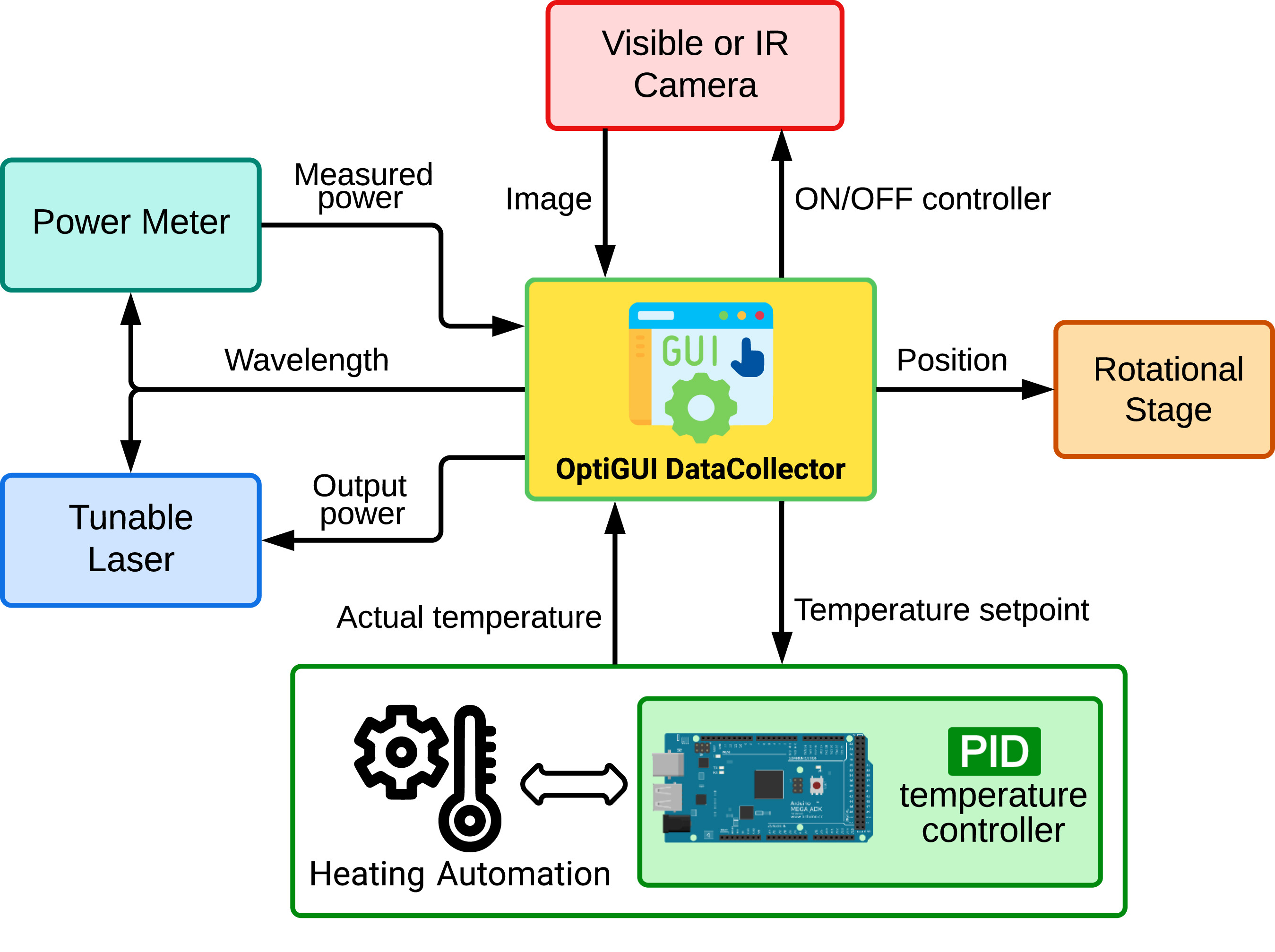
Python modules are used to build the GUI. These modules are designed to work together so that the code can focus on performing the required functions. The user interface (UI) was created using a methodology involving an iterative process, as detailed in the schematic shown in Fig. 1.
|
In addition, the following five hardware components controlled by the UI are shown in the diagram:
- Tunable laser: A tunable laser is a component of equipment that enables the user to alter the operating wavelengths to suit a variety of optical applications. This is accomplished by specifying a starting and ending wavelength, as well as defining the step to be used for the wavelength sweep. It also enables the user to adjust the output power of the light source.
- Power meter: The user may select either the optical power meter or the optical spectrum analyzer. In both instances, the user can configure the interface by providing the initial wavelength, the final wavelength, and the acquisition interval. These parameters should, ideally, correspond to the configuration of the adjustable laser. It is crucial to note that the optical power meter measures the output power of the light source at a specific wavelength, whereas the optical spectrum analyzer measures the power spectrum. Consequently, the choice between the two will depend on the user’s particular measurement needs.
- Rotational stage: This component facilitates the activation of the rotational stage. This rotatable platform allows for a degree-by-degree adjustment of the angle at which certain optical elements are positioned. The user can therefore adjust the initial angle, the final angle, and the step size.
- Visible or IR camera: The component is a power on/off switch for a camera. The camera is a commonly used device for capturing images in different applications, such as capturing images of the spatial distribution of modes propagating in an optical fiber.
- Temperature controlled system: This module contains the hardware components necessary for closed-loop temperature control. It is composed of an Arduino Mega 2560 coupled to a 12 V (40 W) ceramic cartridge heater for heating the fiber (via the RAMPS 1.4 power control board) and a 100 K NTC thermistor for measuring the temperature. The ceramic cartridge heater is encapsulated in an aluminum block containing the fiber to ensure uniform heat distribution. To monitor the actual temperature, a thermistor is also housed in the same block.
The Arduino script is programmed to preprocess and convert the thermistor signal to °C. PID control is then implemented to maintain a constant temperature set point. The Arduino continuously receives this set point via the serial port, which is dynamically adjusted based on the user-specified temperature range in °C via the Python script. Essentially, the Arduino's main function is to maintain temperature control at the specified set point.
Software architecture
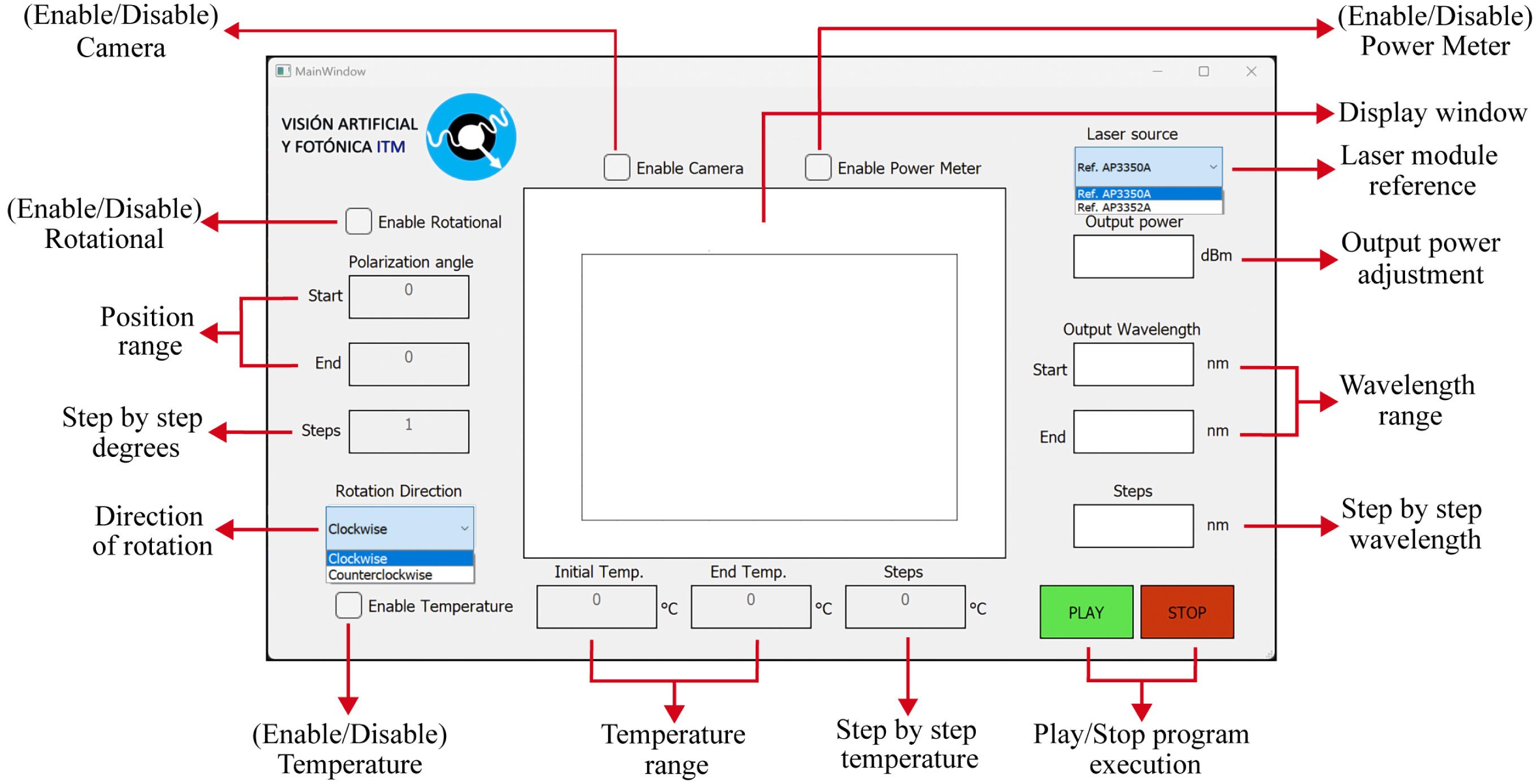
As shown in Fig. 2, OptiGUI DataCollector is a software that incorporates five distinct optical laboratory instruments and enables their control from a single interactive UI. The program's GUI allows the user to automate and control the optical setup intuitively.
|
This window allows the user to configure parameters such as optical power, wavelength, temperature, and any other variables required to change the operation of each device. These values can be saved and reloaded for subsequent experiments, making the program extremely versatile and useful for R&D activities.
Communication between optical equipment and the UI is performed using instrument-specific protocols and libraries. The SDK (software development kit) consists of a compiler, debugger, documentation, drivers, and network protocols for a particular hardware component. A Python-based, object-oriented API (application programming interface) facilitates the project's scalability by facilitating packet exchange. Using a simple access protocol, the user and the instrument exchange information.
The UI consists of seven modules, each of which performs a specific purpose, as described below:
Module 1. Tunable_Laser.py: The TCP/IP protocol over Ethernet is used to communicate with the tunable laser. This protocol allows the simultaneous exchange of data between the UI and the server (Laser PyApex). This feature is made possible by the Python 3-written SDK from Apex Technologies. The SDK comprises a collection of examples Apex1000 device-controlling codes.
The tunable laser module is responsible for setting the characteristic attributes of the laser, such as input power in dBm and operating wavelengths in nm. In addition, it has a drop-down menu for selecting the laser source reference.
Module 2. Degrees_Polarization.py: To establish communication between the UI and a Thorlabs rotational stage, the thorlabs-apt-device library version 0.3.3 is used, which implements the Advanced Positioning Technology (APT) protocol for this type of device. With this library, the Degrees polarization.py module was created to govern the rotational stage using four distinct attributes: initial angle, final angle, steps, and rotational direction. This module allows communication with any device using a DC servo motor driver from Thorlabs. Additionally, the module includes error checking and validation to guarantee correct input and avoid errors during execution. The GUI offers visual feedback and user-friendly controls for simple rotational stage operation.
Module 3. Power_Meter.py: An optical power meter is also used in this UI. This equipment has its drivers in LabVIEW, a development environment that uses a graphical programming language to design systems. To integrate Python with LabVIEW, the “outside-in” function is used, which allows Python to instruct LabVIEW to perform an action and return its result.
To use this integration approach, the “autoliv” and “Activex” libraries are used to retrieve and manipulate data acquired with LabVIEW in Python. The interface also includes a plotter that displays the transmission spectrum plot, where the wavelength and optical power are connected. Each power value corresponding to a wavelength is added to a list to visualize the optical device's transmission spectrum.
Module 4. Image_Capture.py: This module contains two classes for controlling a camera from the system UI. One is responsible for activating the camera in the system and capturing frames, while the other checks the data and stores it in a list data structure. This module also makes use of the OpenCV library to read and save .tiff pictures. Furthermore, the pixel data is saved as a data structure in an array using the numpy library. The module also enables the user to view the images in a window that is generated within the UI.
The use of the OpenCV library provides a wide range of features for processing and analyzing camera images. Image filtering, object detection, and picture segmentation are examples of such characteristics. The acquired frames can also be analyzed in real-time using the library 's functions, allowing the user to perform tasks such as object tracking or motion detection.
Module 5. Temperature_Control: This module is designed to connect to the Arduino Mega through serial communication using the pySerial library. A new object named “mega” is created, which specifies the serial port attributes, the baud rate (115200), and a timeout of one second.
To initiate the connection and send the temperature setpoint, the Python function “mega.write()” is used. On the other hand, to receive the actual temperature read by the thermistor, the “mega.readline()” function is employed.
Here, it is worth noting that the use of the pySerial library enables the communication between the Arduino Mega and Python, allowing the integration of different technologies and enabling software developers to design more comprehensive and efficient solutions. After establishing a connection between the Python script and the Arduino board, the script runs through a user-defined range of temperatures. Each set point is sent individually to the Arduino, and after the arrival signal at the desired temperature, a stabilization time is expected. After this interval, the image and actual temperature are captured and saved in the dataset, and so on for all temperature set points.
Module 6. Execution.py: This module serves as the central control hub for the entire system. It handles all the initialization tasks required to start the program and connects all the modules described above. The module provides access to different system attributes, including wavelengths, camera control, angles, rotation direction, and PLAY and STOP functions.
These attributes play a critical role in the operation of the system. For example, the wavelengths are used “to tell” the system what range of electromagnetic radiation to look for, while the camera control attribute indicates if whether or not the camera will be used. The angles and direction of rotation are used to control how the system moves, allowing it to collect data from different angles. Finally, the PLAY and STOP functions allow users to start or stop the system as needed.
Module 7. Principal_Inteface.py: This is the interface where applications and users interact. It contains all the PyQt5 widgets needed to create the application window. As shown in Fig. 3, the components are organized in a hierarchical structure, where the left-hand side is composed of elementary widgets to control the camera and the rotational stage, respectively. In the middle of the main window, there is a container widget for displaying images and graphs. On the right-hand side are the power meter and the tunable laser control element, and at the bottom of the window are the temperature control elements. The PLAY button starts the program by sending an input function that obtains the system parameters. Having a GUI makes it easy for users to interact with the system and verify its operation.
|
Software functionalities
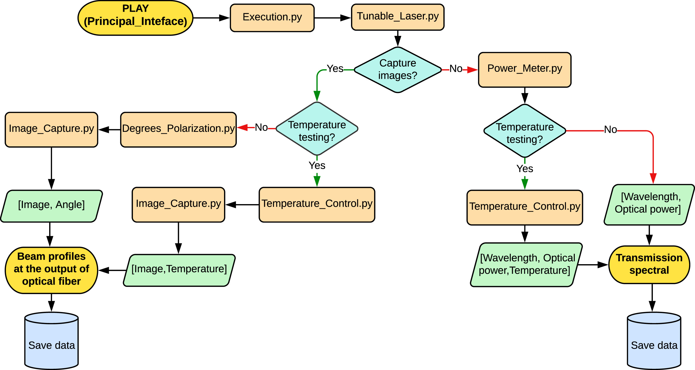
The system flowchart, shown in Fig. 4, describes the process that starts with the PLAY button and allows the activation of the Tunable_Laser.py module.
|
The system has two independent case studies that are described below:
- Case 1: In this situation, the system determines if camera verification is enabled. If it is not, the Power_Meter.py module is run to measure the strength of the laser signal. Next, the system checks if the user has provided the temperature data (temperature range and step-by-step temperature). If so, the Temperature_Control.py module is run to regulate the temperature of the medium and record the transmission spectrum as a function of temperature. The Temperature_Control.py module is skipped if no temperature information is provided, and the transmission spectrum at a given temperature is displayed on the main screen.
- Case 2: In this case, the system checks if the camera verification is active. If so, the Image_Capture.py module is activated to capture the sample image. Then, the system checks if the user has entered the temperature data (temperature range and step-by-step temperature). If so, the Temperature_Control.py module is executed to control the sample temperature and record the sample image as a function of temperature. If no temperature data is entered, the Temperature_Control.py module is skipped and the sample image is shown on the main screen. If no temperature values are entered, but the camera check is active, the Degrees_Polarization.py module is activated to measure the polarization angle of the sample.
In any scenario, the user can modify the input parameters of the system and examine the results in real time, simplifying decision-making and data interpretation. The system is an effective instrument for performing optical measurements over a range of temperatures and polarization angles simultaneously.
Illustrative examples
In this section, one case of how the developed software can be used for data acquisition will be presented, and the operation of the GUI with the included modules will be demonstrated (other illustrative examples are provided as supplementary material). This example uses an experimental setup to perform the investigation of the transmission spectra of a LPFG-based modal conversor.
The validation experiment was conducted using a tunable laser from APEX Technologies, specifically utilizing the AP3350 A or AP3352 A models. The laser allowed adjustments to both the wavelength, spanning from 1526 nm to 1608 nm, and the output power, which ranged from −30 dBm to +13 dBm. In addition, a Thorlabs linear polarizer was mounted on a monitored rotational station (Motor Rotation Stage PRM1Z8) to adjust the polarization of the light at the system's output. This station is equipped with a DC servo motor controller that allows Python-based computer control. It is then feasible to rotate the polarization plane of the light as it exits the LPFGs. In addition, the use of the computerized controller in Python simplifies the adjustment process and allows for improved measurement repeatability. The Thorlabs Motorized Rotation Stage PRM1Z8 enables high-precision rotation with a maximum speed of 25 degrees per second and an accuracy of 0.1%.
On the other hand, identical wavelength values are assigned to both the tunable laser and the EXFO1600 high-speed power meter employed in this experiment. As illustrated in Fig. 4, the power meter is located at the output of the LPFG and is connected to the GUI through a serial connection. In addition, the use of a high-speed power meter such as the EXFO1600 enables fast data capture and accurate measurement of the LPFG output power.
To examine the impact of temperature on the fiber, a PID control system was developed. A 12 V heater and a temperature sensor compose this feedback control system (100 K thermistor). A microcontroller performs PID control with the heater and thermistor (Arduino Mega 2560). Arduino is responsible for managing the temperature based on a set point once the PID control has been implemented. Finally, Python was used to automate the serial transmission of a series of temperature set-points to the Arduino, after confirming that the temperature had stabilized at the desired level.
Measuring transmission spectra at different temperatures using an LPFG
The LPFG transmission spectra were measured at different temperatures using a feedback-controlled heating system and an optical power meter, as shown in the prior Fig. 3. The power meter utilized the same wavelength values assigned to the tunable laser, ensuring precision and consistency in the measurements. The transmission spectrum was measured once the required temperature setting was achieved, and this procedure was repeated at different temperatures to evaluate the changes in the transmission spectrum. The obtained results allowed for quantification of the temperature dependency of LPFG transmission, with data only collected when the temperature increased.
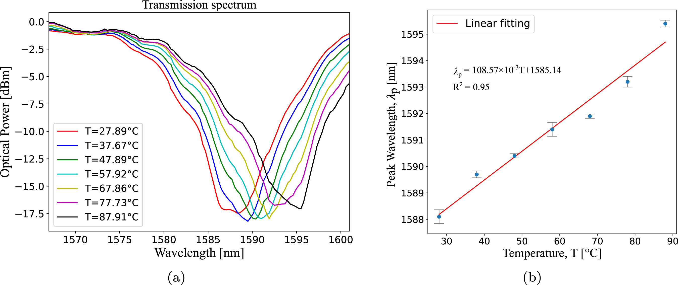
In this context, the GUI was used with the Tunable_Laser.py, Power_Meter.py, and Temperature_Control modules to reconstruct the LPFG transmission spectra while varying the temperature from 28 °C to 88 °C. To reconstruct the transmission spectra of the LPFG, a laser power of 13 dBm was assigned, while the wavelength varied from 1527 nm to 1601 nm with steps of 0.3 nm. Based on this, power data were collected using a power meter to reconstruct the LPFG transmission spectra for seven different temperatures. As shown in Fig. 5(a), the resonant wavelength of the LPFG exhibited a shift towards longer wavelengths, as expected.[2][3]
|
To guarantee that the experiment could be repeated with the same results, measurements were performed five times for each temperature value. The experiments were conducted randomly to reduce the effect of any external influences that could have an impact on the accuracy and reproducibility of the results. Fig. 5(b) shows the sensitivity curve of the LPFG-based temperature sensor, which demonstrates a sensitivity very close to 108.57 pm/°C. In Fig. 5(b), the mean value is shown, and the bars surrounding each point illustrate the range of error that can be expected from the measurement. In all cases, the range of error is quite small. This suggests that the experiment can be repeated with a high degree of accuracy, and the software that was developed allows a greater degree of control over the experiment, further enhancing its repeatability. It is important to note that the time required to acquire data is around 18 minutes for each data set.
Impact
OptiGUI DataCollector offers researchers in photonics and optoelectronics areas a variety of advantages. By automating repetitive and time-consuming tasks such as data acquisition, processing, and analysis, researchers can save significant time and effort when conducting experiments. This increased productivity can result in accelerated research progress and more accurate and reliable findings. In addition, the software enables researchers to conduct complex investigations that may be difficult or impossible to conduct manually.
Another benefit of automation is the reduction of human errors, which can have a significant impact on the reliability of experimental results. By automating data collection and analysis, OptiGUI DataCollector reduces the possibility of errors, resulting in more precise and reliable findings. In addition, the OptiGUI DataCollector's easy-to-user interfaces and automation tools to make photonics and optoelectronics research accessible to a broader spectrum of researchers, including those with limited technical expertise.
Conclusions
To summarize, OptiGUI DataCollector is a flexible and powerful experiment control software application that offers significant benefits to photonics and optoelectronics R&D personnel. Its modular design simplifies the construction of new experiments and reduces the effort required to set up an experiment. The software's automation capabilities accelerate data acquisition, processing, and analysis, saving researchers time and effort. The software reduces human error, improves reproducibility, and provides flexibility and customization options. OptiGUI DataCollector could be a useful tool that can accelerate research progress, and improve the veracity of findings in R&D labs that focus on photonics, optics, and optoelectronics.
Code metadata
- Current code version: v1.0
- Permanent link to code/repository used for this code version: https://github.com/ElsevierSoftwareX/SOFTX-D-23-00293
- Code Ocean compute capsule: none
- Legal Code License: GNU (GPL)
- Code versioning system used: Git
- Software code languages, tools, and services used: Python 3.8, LabView
- Compilation requirements, operating environments & dependencies: See User Manual in GitHub repository
- If available Link to developer documentation/manual: See User Manual in GitHub repository
- Support email for questions: juansoto319998 at correo dot itm dot edu dot co
Supplementary data
- Video S1. This video (.mp4) contains additional examples of OptiGUI Data Collector.
- Illustrative Examples (.pdf)
Acknowledgements
The authors acknowledge the support of Instituto Tecnologico Metropolitano, through project P20212, and the Universidad Nacional de Colombia, through Hermes project 47472.
Data availability
Data will be made available on request.
Competing interests
The authors declare that they have no known competing financial interests or personal relationships that could have appeared to influence the work reported in this paper.
References
- ↑ Arango, Juan; Aristizabal, Victor; Vélez, Francisco; Carrasquilla, Juan; Gomez, Jorge; Quijano, Jairo; Herrera-Ramirez, Jorge (1 June 2023). "Synthetic dataset of speckle images for fiber optic temperature sensor" (in en). Data in Brief 48: 109134. doi:10.1016/j.dib.2023.109134. PMC PMC10139894. PMID 37122920. https://linkinghub.elsevier.com/retrieve/pii/S2352340923002536.
- ↑ 2.0 2.1 Valencia-Garzón, Sebastian; Reyes-Vera, Erick; Galvis-Arroyave, Jorge; Montoya, Jose P.; Gomez-Cardona, Nelson (27 November 2022). "Metrological Characterization of a CO2 Laser-Based System for Inscribing Long-Period Gratings in Optical Fibers" (in en). Instruments 6 (4): 79. doi:10.3390/instruments6040079. ISSN 2410-390X. https://www.mdpi.com/2410-390X/6/4/79.
- ↑ 3.0 3.1 Del Villar, Ignacio; Montoya-Cardona, Jorge; Imas, José J.; Reyes-Vera, Erick; Zamarreño, Carlos R.; Matias, Ignacio R.; Cruz, Jose L. (1 July 2023). "Tunable Sensitivity in Long Period Fiber Gratings During Mode Transition With Low Refractive Index Intermediate Layer". Journal of Lightwave Technology 41 (13): 4219–4229. doi:10.1109/JLT.2022.3226800. ISSN 0733-8724. https://ieeexplore.ieee.org/document/9970326/.
- ↑ Reyes-Vera, Erick; Botero-Valencia, Juan S.; Arango-Bustamante, Karen; Zuluaga, Alejandra; Naranjo, Tonny W. (29 April 2022). "Microscopic Imaging and Labeling Dataset for the Detection of Pneumocystis jirovecii Using Methenamine Silver Staining Method" (in en). Data 7 (5): 56. doi:10.3390/data7050056. ISSN 2306-5729. https://www.mdpi.com/2306-5729/7/5/56.
- ↑ Muñoz-Hernández, Tatiana; Reyes-Vera, Erick; Torres, Pedro (19 August 2019). "Tunable Whispering Gallery Mode Photonic Device Based on Microstructured Optical Fiber with Internal Electrodes" (in en). Scientific Reports 9 (1): 12083. doi:10.1038/s41598-019-48598-z. ISSN 2045-2322. PMC PMC6700125. PMID 31427674. https://www.nature.com/articles/s41598-019-48598-z.
- ↑ Arango, J D; Aristizabal, V H; Carrasquilla, J F; Gomez, J A; Quijano, J C; Velez, F J; Herrera-Ramirez, J (1 December 2021). "Deep learning classification and regression models for temperature values on a simulated fibre specklegram sensor". Journal of Physics: Conference Series 2139 (1): 012001. doi:10.1088/1742-6596/2139/1/012001. ISSN 1742-6588. https://iopscience.iop.org/article/10.1088/1742-6596/2139/1/012001.
- ↑ Montoya, Manuel; Lopera, Maria J.; Gómez-Ramírez, Alejandra; Buitrago-Duque, Carlos; Pabón-Vidal, Adriana; Herrera-Ramirez, Jorge; Garcia-Sucerquia, Jorge; Trujillo, Carlos (1 June 2023). "FocusNET: An autofocusing learning‐based model for digital lensless holographic microscopy" (in en). Optics and Lasers in Engineering 165: 107546. doi:10.1016/j.optlaseng.2023.107546. https://linkinghub.elsevier.com/retrieve/pii/S0143816623000751.
- ↑ Galvis-Arroyave, J L; Villegas-Aristizabal, J; Montoya-Cardona, J; Montoya-Villada, S; Reyes-Vera, E (1 May 2020). "Experimental characterization of a tuneable all-fiber mode converter device for mode-division multiplexing systems". Journal of Physics: Conference Series 1547 (1): 012004. doi:10.1088/1742-6596/1547/1/012004. ISSN 1742-6588. https://iopscience.iop.org/article/10.1088/1742-6596/1547/1/012004.
- ↑ Gómez-Cardona, Nelson; Jiménez-Durango, Cristian; Usuga-Restrepo, Juan; Torres, Pedro; Reyes-Vera, Erick (1 February 2021). "Thermo-optically tunable polarization beam splitter based on selectively gold-filled dual-core photonic crystal fiber with integrated electrodes" (in en). Optical and Quantum Electronics 53 (2): 68. doi:10.1007/s11082-020-02718-6. ISSN 0306-8919. http://link.springer.com/10.1007/s11082-020-02718-6.
- ↑ 10.0 10.1 Binder, Jan M.; Stark, Alexander; Tomek, Nikolas; Scheuer, Jochen; Frank, Florian; Jahnke, Kay D.; Müller, Christoph; Schmitt, Simon et al. (2017). "Qudi: A modular python suite for experiment control and data processing" (in en). SoftwareX 6: 85–90. doi:10.1016/j.softx.2017.02.001. https://linkinghub.elsevier.com/retrieve/pii/S2352711017300055.
- ↑ 11.0 11.1 Bromig, Lukas; Leiter, David; Mardale, Alexandru-Virgil; von den Eichen, Nikolas; Bieringer, Emmeran; Weuster-Botz, Dirk (1 January 2022). "The SiLA 2 Manager for rapid device integration and workflow automation" (in en). SoftwareX 17: 100991. doi:10.1016/j.softx.2022.100991. https://linkinghub.elsevier.com/retrieve/pii/S2352711022000103.
- ↑ 12.0 12.1 Colle, Jean-Yves; Rautio, Jouni; Freis, Daniel (1 December 2021). "A modular LabVIEW application frame for Knudsen Effusion Mass Spectrometry instrument control" (in en). SoftwareX 16: 100875. doi:10.1016/j.softx.2021.100875. https://linkinghub.elsevier.com/retrieve/pii/S2352711021001412.
- ↑ 13.0 13.1 Killoran, Nathan; Izaac, Josh; Quesada, Nicolás; Bergholm, Ville; Amy, Matthew; Weedbrook, Christian (11 March 2019). "Strawberry Fields: A Software Platform for Photonic Quantum Computing" (in en). Quantum 3: 129. doi:10.22331/q-2019-03-11-129. ISSN 2521-327X. https://quantum-journal.org/papers/q-2019-03-11-129/.
- ↑ 14.0 14.1 Gomez Labat, J. (2016). "Desarrollo de una interfaz gráfica de usuario para el control de analizadores de espectros ópticos mediante Matlab". Academica-e. Universidad Pública de Navarra - Nafarroako Unibertsitate Publikoa. Archived from the original on 10 December 2023. https://web.archive.org/web/20231210081252/https://academica-e.unavarra.es/xmlui/handle/2454/21691.
- ↑ 15.0 15.1 Harun S.W., Emami S.D., Arof H., Hajireza P., Ahmad H. (21 January 2011), de Asmundis, Riccardo, ed., "LabVIEW Applications for Optical Amplifier Automated Measurements, Fiber-Optic Remote Test and Fiber Sensor Systems" (in en), Modeling, Programming and Simulations Using LabVIEW™ Software (InTech), doi:10.5772/13247, ISBN 978-953-307-521-1, http://www.intechopen.com/books/modeling-programming-and-simulations-using-labview-software/labview-applications-for-optical-amplifier-automated-measurements-fiber-optic-remote-test-and-fiber-
Notes
This presentation is faithful to the original, with only a few minor changes to presentation. In some cases important information was missing from the references, and that information was added. In the original, Figure 3 and 4 are mentioned out of order; they have been swapped for this version.
