Difference between revisions of "Journal:OptiGUI DataCollector: A graphical user interface for automating the data collecting process in optical and photonics labs"
Shawndouglas (talk | contribs) (Saving and adding more.) |
Shawndouglas (talk | contribs) (Saving and adding more.) |
||
| Line 40: | Line 40: | ||
==Software description== | ==Software description== | ||
OptiGUI DataCollector is a GUI created using [[Python (programming language)|Python 3.8]], the PyQt5 library, and QTDesigner. This GUI uses an object-oriented programming paradigm to create a framework that is unique. The GUI allows the user to intuitively operate the basic functions of the most used instruments in a photonics [[laboratory]], minimizing the time required to obtain data through continuous interaction with the instruments. In addition, the GUI design allows easy reuse of existing modules and implementation with other hardware controllers, allowing the use of equipment from other manufacturers. | |||
The user can acquire optical power and image data for different wavelengths and polarization states of light, as well as subject optical devices to different temperature changes to analyze variations in the characteristics of light as it propagates through an optical fiber. In addition, OptiGUI DataCollector allows exporting the data collected during the experiment for further study. This UI allows R&D personnel to automate and streamline their studies of fiber optic devices. | |||
===Framework components=== | |||
Python modules are used to build the GUI. These modules are designed to work together so that the code can focus on performing the required functions. The user interface (UI) was created using a methodology involving an iterative process, as detailed in the schematic shown in Fig. 1. | |||
[[File:Fig1 Soto-Perdomo SoftwareX2023 24.jpg|700px]] | |||
{{clear}} | |||
{| | |||
| style="vertical-align:top;" | | |||
{| border="0" cellpadding="5" cellspacing="0" width="700px" | |||
|- | |||
| style="background-color:white; padding-left:10px; padding-right:10px;" |<blockquote>'''Figure 1.''' Diagram of the framework components with their respective input and output parameters.</blockquote> | |||
|- | |||
|} | |||
|} | |||
In addition, the following five hardware components controlled by the UI are shown in the diagram: | |||
* '''Tunable laser''': A tunable laser is a component of equipment that enables the user to alter the operating wavelengths to suit a variety of optical applications. This is accomplished by specifying a starting and ending wavelength, as well as defining the step to be used for the wavelength sweep. It also enables the user to adjust the output power of the light source. | |||
* '''Power meter''': The user may select either the optical power meter or the optical spectrum analyzer. In both instances, the user can configure the interface by providing the initial wavelength, the final wavelength, and the acquisition interval. These parameters should, ideally, correspond to the configuration of the adjustable laser. It is crucial to note that the optical power meter measures the output power of the light source at a specific wavelength, whereas the optical spectrum analyzer measures the power spectrum. Consequently, the choice between the two will depend on the user’s particular measurement needs. | |||
* '''Rotational stage''': This component facilitates the activation of the rotational stage. This rotatable platform allows for a degree-by-degree adjustment of the angle at which certain optical elements are positioned. The user can therefore adjust the initial angle, the final angle, and the step size. | |||
* '''Visible or IR camera''': The component is a power on/off switch for a camera. The camera is a commonly used device for capturing images in different applications, such as capturing images of the spatial distribution of modes propagating in an optical fiber. | |||
* '''Temperature controlled system''': This module contains the hardware components necessary for closed-loop temperature control. It is composed of an Arduino Mega 2560 coupled to a 12 V (40 W) ceramic cartridge heater for heating the fiber (via the RAMPS 1.4 power control board) and a 100 K NTC thermistor for measuring the temperature. The ceramic cartridge heater is encapsulated in an aluminum block containing the fiber to ensure uniform heat distribution. To monitor the actual temperature, a thermistor is also housed in the same block. | |||
The Arduino script is programmed to preprocess and convert the thermistor signal to °C. PID control is then implemented to maintain a constant temperature set point. The Arduino continuously receives this set point via the serial port, which is dynamically adjusted based on the user-specified temperature range in °C via the Python script. Essentially, the Arduino's main function is to maintain temperature control at the specified set point. | |||
===Software architecture=== | |||
Revision as of 23:23, 26 March 2024
| Full article title | OptiGUI DataCollector: A graphical user interface for automating the data collecting process in optical and photonics labs |
|---|---|
| Journal | SoftwareX |
| Author(s) | Soto-Perdomo, Juan; Morales-Guerra, Juan; Arango, Juan D.; Villada, Sebastian M.; Torres, Pedro; Reyes-Vera, Erick |
| Author affiliation(s) | Instituto Tecnológico Metropolitano, Universidad Nacional de Colombia |
| Primary contact | Email: juansoto319998 at correo dot itm dot edu dot co |
| Year published | 2023 |
| Volume and issue | 24 |
| Article # | 101521 |
| DOI | 10.1016/j.softx.2023.101521 |
| ISSN | 2352-7110 |
| Distribution license | Creative Commons Attribution 4.0 International |
| Website | https://www.sciencedirect.com/science/article/pii/S2352711023002170 |
| Download | https://www.sciencedirect.com/science/article/pii/S2352711023002170/pdfft (PDF) |
|
|
This article should be considered a work in progress and incomplete. Consider this article incomplete until this notice is removed. |
Abstract
OptiGUI DataCollector is a Python 3.8-based graphical user interface (GUI) that facilitates automated data collection in optics and photonics research and development equipment. It provides an intuitive and easy-to-use platform for controlling a wide range of optical instruments, including spectrometers and lasers. OptiGUI DataCollector is a flexible and modular framework that enables simple integration with different types of devices. It simplifies experimental workflow and reduces human error by automating parameter control, data acquisition, and analysis. OptiGUI DataCollector is currently focused on optical mode conversion utilizing fiber optic technologies but can be expanded to other research and development (R&D) processes.
Keywords: laboratory automation, device integration, software framework, graphical user interface, optical fiber, optical mode conversion
Motivation and significance
Experiments in today's scientific research are becoming increasingly complicated and involve several hardware devices that work together in a coordinated manner. These experiments can contain a variety of instruments such as sensors, analyzers, detectors, and actuators, each of which has a specific purpose in the experiment. [1–9] Efficiently controlling these experiments demands software that can effectively coordinate the functioning of these devices, not only by delivering orders but also by ensuring accurate data collection and control of experimental conditions. [10–13] The software must be able to handle the communication protocols and data formats of many devices, as well as manage potential conflicts or dependencies between them.
In addition to accurate management, fast data processing and visualization are critical for effective data interpretation. Because experiments create significant amounts of real-time data, the software must be able to process the data rapidly and efficiently. This may include data filtering, standardization, analysis, and visualization to obtain useful insights from the experiment. Real-time data visualization can also provide researchers with quick feedback, allowing them to make informed decisions and modify experimental conditions as needed.
Each experiment requires a unique combination of hardware devices depending on the specific needs of the research. [10–15] Two studies discussed in this passage highlight the development of software interfaces for fiber optic devices. In the first study, Labat [14] created a graphical user interface (GUI) in Matlab that allows for remote control, data acquisition, and data visualization from optical spectrum analyzers. The GUI was implemented to analyze the transmission spectrum of long-period fiber gratings (LPFGs), with various parameters such as operating wavelength and center settings. In the second study, Harun et al. [15] developed an automated system in LabVIEW for self-calibration and measurement of fiber optic devices such as sensors and Erbium Doped Fiber Amplifiers (EDFAs). Their system allows for up to an 80% reduction in data acquisition time while providing precise and consistent measurements with a low uncertainty value of ±0.012 dB.
Based on the above, this work has developed a computerized instrumentation system that allows constant monitoring, processing, and data collection of research and development (R&D) equipment; therefore, we propose an object-oriented GUI capable of executing the tasks dynamically without having to incur system modifications that may disturb the measurements. The purpose of executing various tasks requires employing reliable models to optimize the functions of each of the instruments, allowing the efficient use of the R&D personnel is working time, as well as providing a user-friendly interface to facilitate the manipulation of the instruments. With object-oriented programming, the problem to be solved is modeled through a series of interactions between the optical equipment, reusing lines of code through inheritance, and the implementation of polymorphism.
Software description
OptiGUI DataCollector is a GUI created using Python 3.8, the PyQt5 library, and QTDesigner. This GUI uses an object-oriented programming paradigm to create a framework that is unique. The GUI allows the user to intuitively operate the basic functions of the most used instruments in a photonics laboratory, minimizing the time required to obtain data through continuous interaction with the instruments. In addition, the GUI design allows easy reuse of existing modules and implementation with other hardware controllers, allowing the use of equipment from other manufacturers.
The user can acquire optical power and image data for different wavelengths and polarization states of light, as well as subject optical devices to different temperature changes to analyze variations in the characteristics of light as it propagates through an optical fiber. In addition, OptiGUI DataCollector allows exporting the data collected during the experiment for further study. This UI allows R&D personnel to automate and streamline their studies of fiber optic devices.
Framework components
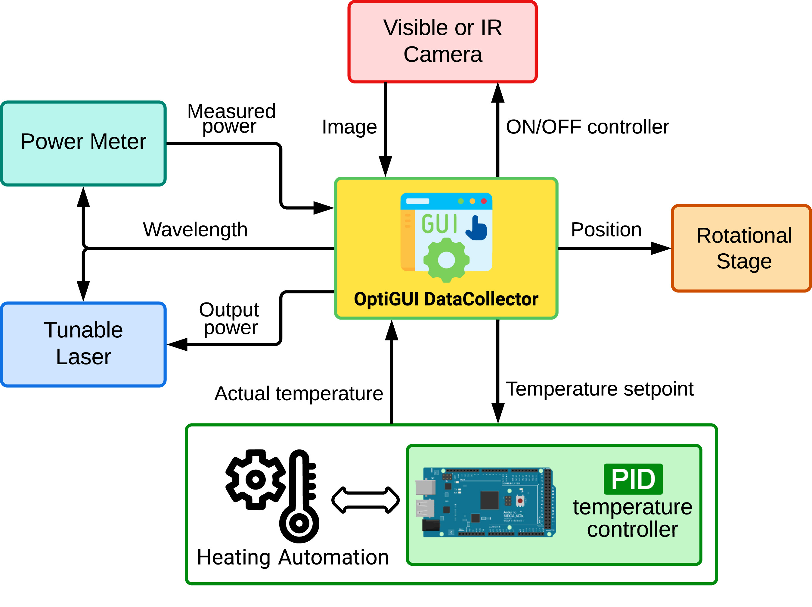
Python modules are used to build the GUI. These modules are designed to work together so that the code can focus on performing the required functions. The user interface (UI) was created using a methodology involving an iterative process, as detailed in the schematic shown in Fig. 1.
|
In addition, the following five hardware components controlled by the UI are shown in the diagram:
- Tunable laser: A tunable laser is a component of equipment that enables the user to alter the operating wavelengths to suit a variety of optical applications. This is accomplished by specifying a starting and ending wavelength, as well as defining the step to be used for the wavelength sweep. It also enables the user to adjust the output power of the light source.
- Power meter: The user may select either the optical power meter or the optical spectrum analyzer. In both instances, the user can configure the interface by providing the initial wavelength, the final wavelength, and the acquisition interval. These parameters should, ideally, correspond to the configuration of the adjustable laser. It is crucial to note that the optical power meter measures the output power of the light source at a specific wavelength, whereas the optical spectrum analyzer measures the power spectrum. Consequently, the choice between the two will depend on the user’s particular measurement needs.
- Rotational stage: This component facilitates the activation of the rotational stage. This rotatable platform allows for a degree-by-degree adjustment of the angle at which certain optical elements are positioned. The user can therefore adjust the initial angle, the final angle, and the step size.
- Visible or IR camera: The component is a power on/off switch for a camera. The camera is a commonly used device for capturing images in different applications, such as capturing images of the spatial distribution of modes propagating in an optical fiber.
- Temperature controlled system: This module contains the hardware components necessary for closed-loop temperature control. It is composed of an Arduino Mega 2560 coupled to a 12 V (40 W) ceramic cartridge heater for heating the fiber (via the RAMPS 1.4 power control board) and a 100 K NTC thermistor for measuring the temperature. The ceramic cartridge heater is encapsulated in an aluminum block containing the fiber to ensure uniform heat distribution. To monitor the actual temperature, a thermistor is also housed in the same block.
The Arduino script is programmed to preprocess and convert the thermistor signal to °C. PID control is then implemented to maintain a constant temperature set point. The Arduino continuously receives this set point via the serial port, which is dynamically adjusted based on the user-specified temperature range in °C via the Python script. Essentially, the Arduino's main function is to maintain temperature control at the specified set point.
Software architecture
Code metadata
- Current code version: v1.0
- Permanent link to code/repository used for this code version: https://github.com/ElsevierSoftwareX/SOFTX-D-23-00293
- Code Ocean compute capsule: none
- Legal Code License: GNU (GPL)
- Code versioning system used: Git
- Software code languages, tools, and services used: Python 3.8, LabView
- Compilation requirements, operating environments & dependencies: See User Manual in GitHub repository
- If available Link to developer documentation/manual: See User Manual in GitHub repository
- Support email for questions: juansoto319998 at correo dot itm dot edu dot co
References
Notes
This presentation is faithful to the original, with only a few minor changes to presentation. In some cases important information was missing from the references, and that information was added.
